Control Flow Graphs (CFG)
A control flow graph (CFG) is a graph where each node corresponds to one basic block of code, and each edge represents a possible control flow transfer. This way, a control flow graph tries to encode all possible execution paths in a chunk of code, method or entire program.
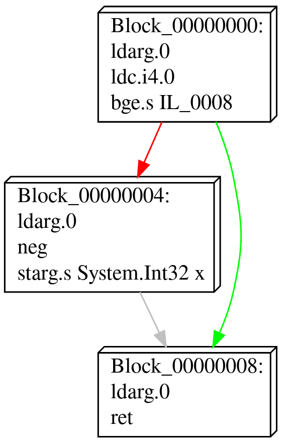
The figure below depicts a control flow graph of a very simple if-statement:
Graphs
Every control flow graph is represented using the ControlFlowGraph<TInstruction> class.
A new, empty graph can be created by using one of the constructors.
var cfg = new ControlFlowGraph<TInstruction>();
To extract a control flow graph from an existing code stream, this depends per platform. Refer to the platform-specific documentation for more details.
Nodes
Nodes in a control flow graph represent the individual basic blocks in the code, and are implemented by the ControlFlowNode<TInstruction> class.
They can be accessed from the Nodes property, which can be iterated:
ControlFlowGraph<TInstruction> cfg = ...;

// Iterate over all nodes in a control flow graph:
foreach (var node in cfg.Nodes)
    Console.WriteLine($"{node.Offset:X8}");
Individual nodes can be obtained by looking them up by offset:
var node = cfg.Nodes.GetByOffset(offset: 0x1234);
This performs a linear search through all the nodes, and finds the first basic block that matches.
To ensure all nodes have updated offsets according to their contents, use the UpdateOffsets method:
cfg.Nodes.UpdateOffsets();
When doing many lookups by offset, consider first creating an offset map for faster lookups.
var offsetMap = cfg.Nodes.CreateOffsetMap();
var n1 = offsetMap[0x0001];
var n2 = offsetMap[0x0004];
var n3 = offsetMap[0x0010];
Every node exposes a basic block containing the instructions it executes:
ControlFlowNode<TInstruction> node = ...;

// Iterate over all instructions within the block.
foreach (var instruction in node.Contents.Instructions)
    Console.WriteLine(instruction);
Edges
Nodes are connected to each other with edges, represented by the ControlFlowEdge<TInstruction> class.
There are four types of edges Echo distinguishes:
| Type | Description |
|---|---|
FallThrough |
An edge implicitly introduced by a block that falls through into the next one. |
Unconditional |
An edge introduced by an unconditional jump/branch instruction. |
Conditional |
An edge introduced by a conditional jump/branch instruction. |
Abnormal |
An edge introduced by special or exceptional control flow (such as an error or signal). |
Individual edges can be obtained by accessing their respective properties:
ControlFlowNode<TInstruction> node = ...;

// Obtain the outgoing unconditional or fallthrough edge (if available).
var unconditional = node.UnconditionalEdge;
if (unconditional is not null)
    Console.WriteLine(unconditional);

// Iterate all outgoing conditional edges.
foreach (var conditional in node.ConditionalEdges)
    Console.WriteLine(conditional);

// Iterate all outgoing abnormal edges.
foreach (var abnormal in node.AbnormalEdges)
    Console.WriteLine(abnormal);
Every edge defines a Source and a Target node, allowing for traversing the graph.
ControlFlowEdge<TInstruction> edge = ...;
ControlFlowNode<TInstruction> target = edge.Target;
All outgoing edges can also be obtained at once using GetOutgoingEdges():
foreach (var edge in node.GetOutgoingEdges())
    Console.WriteLine(edge.Target);
If only interested in the target nodes, GetSuccessors() can be used instead:
foreach (var successor in node.GetSuccessors())
    Console.WriteLine(successor);
```[dfg-basics.md](dfg-basics.md)

Similarly, incoming edges can also be obtained using `GetIncomingEdges()` and `GetPredecessors()`:

```csharp
foreach (var edge in node.GetIncomingEdges())
    Console.WriteLine(edge.Source);
foreach (var predecessor in node.GetPredecessors())
    Console.WriteLine(predecessor);
New edges can be drawn by either mutating the outgoing edges properties, or by using the ConnectWith helper method:
ControlFlowNode<TInstruction> node1 = ...;
ControlFlowNode<TInstruction> node2 = ...;
ControlFlowNode<TInstruction> node3 = ...;
ControlFlowNode<TInstruction> node4 = ...;

node1.ConnectWith(node2);
node2.ConnectWith(node3, ControlFlowEdgeType.Conditional);
node2.ConnectWith(node4, ControlFlowEdgeType.FallThrough);
Regions
Control flow graphs can be subdivided into regions. These can either be simple scopes, but also regions protected by an exception handler.
foreach (var region in cfg.Regions)
{
    // ...
}
There are various types of regions:
| Type | Description |
|---|---|
ScopeRegion |
A simple collection of nodes. |
ExceptionHandlerRegion |
A region that is protected by one or more exception handlers. |
HandlerRegion |
A single exception handler. |
Invidiual nodes can be put into a ScopeRegion:
// Define new scope and add it to the graph.
var region = new ScopeRegion<TInstruction>();
cfg.Regions.Add(region);

// Add nodes.
region.Nodes.Add(node1);
region.Nodes.Add(node2);
region.Nodes.Add(node3);

// Define the entry point of the scope.
region.EntryPoint = node1;
Exception handlers comprise multiple regions:
// Define a new exception handler.
var main = new ExceptionHandlerRegion<TInstruction>();
main.Handlers.Add(handler);

// Add a node to the protected region.
main.ProtectedRegion.Nodes.Add(node1);
main.ProtectedRegion.EntryPoint = node1;

// Add a handler.
var handler = new HandlerRegion<TInstruction>();
handler.Nodes.Add(node2);
handler.EntryPoint = node2;
Nodes in a control flow graph are always part of a region.
By default, they are part of the root region, which is the control flow graph itself.
Obtaining the region a node is situated in can be done using the ParentRegion property, or GetSituatedRegions method to get all the regions it is present in:
ControlFlowNode<TInstruction> node = ...

var directParentRegion = node.ParentRegion;
var allRegions = node.GetSituatedRegions();
Testing whether a node belongs to a specific region (including sub regions) can be done using the IsInRegion method:
if (node.IsInRegion(parentRegion))
{
    // ...
}
Visualizing Control Flow Graphs
Echo provides default serializers for graphs in DOT format.
using var writer = File.CreateText("output.dot");
cfg.ToDotGraph(writer);
To customize the way instructions are formatted, use an IInstructionFormatter<TInstruction>:
class MyFormatter : IInstructionFormatter<TInstruction>
{
    public string Format(in TInstruction instruction)
    {
        // ...
    }
}

using var writer = File.CreateText("output.dot");
cfg.ToDotGraph(writer, new MyFormatter());
These can then be visualized using e.g., GraphViz.